Hardware Assembly: Rivets, Snaps and Buckle Setting
Hardware Assembly: Rivets, Snaps and Buckle Setting
Hardware is the smallest component group on a backpack and the most common cause of field failure. A strap that pulls out of its anchor, a snap that will not close, or a buckle that releases under load all trace back to how the hardware was set, not to how the bag was designed.
These operations are manual, repetitive, and difficult to inspect after the fact. A rivet that was set with the wrong die looks correct from the outside and fails after three months of use.
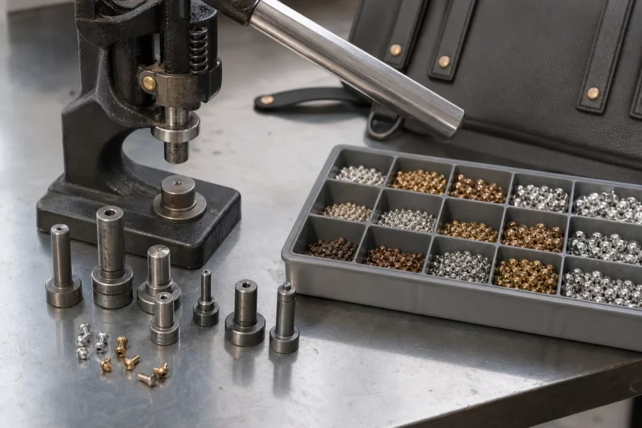
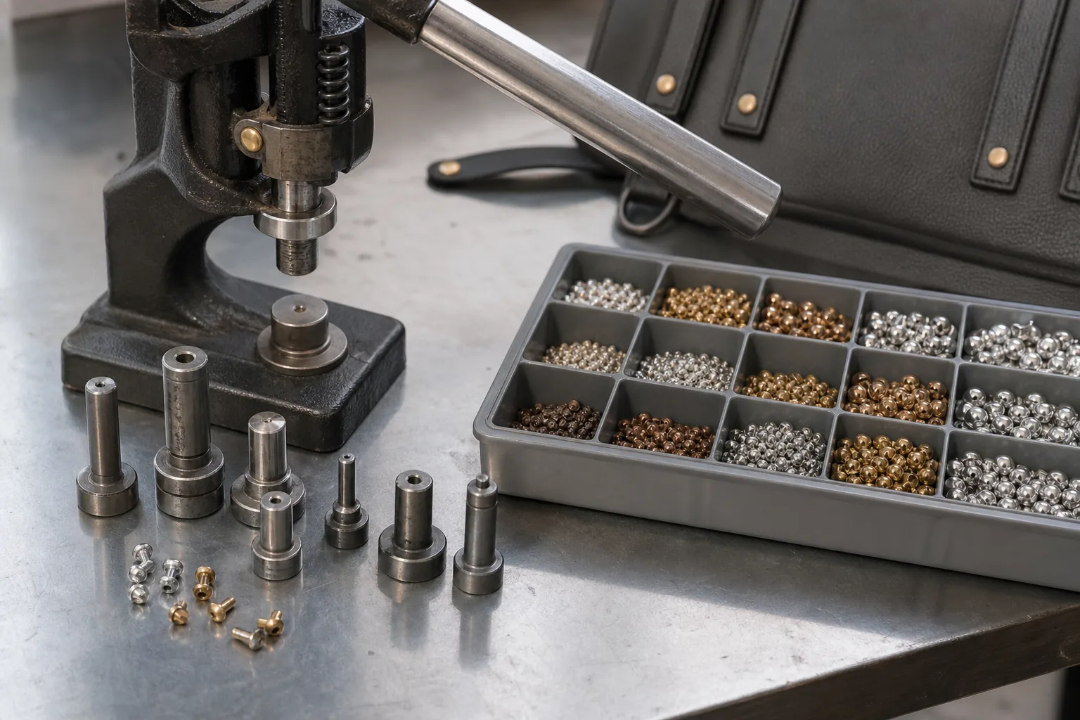
Rivet setting tools and assorted metal rivets on a factory workbench
This guide covers hardware assembly from a bag manufacturer’s perspective: the hardware types used on backpacks, how rivets, snaps, eyelets, and buckles are set, the tooling and force parameters that determine a sound joint, the reinforcement that makes the joint hold, the testing that verifies it, and the quality controls that keep a hardware line consistent across a production run.
Hardware assembly is the point where a well-designed bag becomes either durable or unreliable. The materials and the pattern may be perfect, and a single badly set rivet can still lose the customer.
The Hardware Functions
Component
Function
Rivet
Permanent fastening through layers
Snap fastener
Releasable closure
Eyelet
Reinforced opening
Buckle
Load-bearing adjustable connection
D-ring
Attachment point
Cord lock
Cord adjustment
Zipper pull
Access to closure
The Failure Table
Failure
Root cause
Rivet pulls out
Wrong die, insufficient flare
Rivet crushes the fabric
Excessive force
Snap will not close
Incorrect component pairing
Snap releases under load
Insufficient retention force
Eyelet tears out
Missing reinforcement
Buckle releases in use
Wrong buckle for the load
Strap slips at the buckle
Incorrect webbing thickness
The Assembly Difficulty Table
Operation
Difficulty
Rivet setting
Moderate, die-dependent
Snap setting
Moderate, alignment-critical
Eyelet setting
Moderate
Buckle threading
Low but error-prone
D-ring attachment
Low
Cord lock fitting
Low
Adjuster fitting
Low
The Inspection Limitation Table
Operation
Post-assembly visibility
Rivet
Internal flare hidden
Snap
Retention force hidden
Eyelet
Underside flare hidden
Buckle threading
Route visible
Reinforcement layering
Layering hidden
The Cost Table
Cost element
Influence
Hardware unit cost
Component price
Setting labour
Operation time
Tooling
Die and press
Rework
Defect rate
Warranty claims
Field failures
Factory note: Hardware failures almost never appear at final inspection, because the defect is hidden inside the joint. A rivet set with an undersized flare holds well enough to pass a pull test at the machine and loosens after months of cyclic loading. Preventing that failure depends on die selection and force control at the station, not on inspection afterwards.
Hardware Types and Selection
The hardware specified in the tech pack determines what the assembly stations must achieve. Selection should follow the load and the use case.
The Rivet Types
Type
Use
Tubular rivet
Fabric and webbing joints
Semi-tubular rivet
Thicker material stacks
Solid rivet
High-strength permanent joints
Split rivet
Light-duty fabric anchoring
Blind rivet
Where access is one-sided
Screw rivet
Removable joints
The Rivet Material Table
Material
Character
Brass
Good finish, moderate strength
Steel, plated
High strength, corrosion risk
Stainless steel
Corrosion resistant, harder to set
Aluminium
Light, lower strength
Zinc alloy
Cast components and plates
The Snap Types Table
Type
Use
Ring snap
General closures
Prong snap
Where no flaring is possible
Spring snap
Repeated opening
Magnetic snap
Low-force closures
Hook and loop
Alternative closure system
The Buckle Types Table
Type
Use
Side release
Main straps and belts
Cam buckle
Strap adjustment under load
Ladder lock
Webbing adjustment
Cord lock
Drawcord adjustment
Tension lock
Strap tensioning
Hook
Detachable attachment
The Selection Table
Requirement
Suitable hardware
High load, permanent
Tubular or solid rivet
Repeated opening
Spring snap or side release buckle
Adjustment under load
Cam buckle
Light closure
Ring snap
Cord adjustment
Cord lock
Attachment point
D-ring with rivet
The Compatibility Table
Combination
Consideration
Buckle and webbing width
Must match exactly
Buckle and webbing thickness
Affects slip resistance
Rivet length and stack height
Determines flare
Snap and fabric thickness
Determines closure
Eyelet and material
Determines reinforcement need
The Material Stack Table
Stack
Rivet length rule
Two layers of webbing
Measured stack plus flare allowance
Webbing plus fabric
Measured stack plus flare allowance
Webbing plus leather
Increased allowance
Multiple folded layers
Measure at the thickest point
Setting Rivets
Rivets are the most common permanent hardware joint on a backpack. A sound rivet has a fully formed flare on the blind side and a stack that is neither crushed nor loose.
The Rivet Anatomy Table
Part
Function
Head
Visible side
Shank
Passes through the stack
Tubular end
Forms the flare
Flare or roll
Locks the joint
The Setting Methods Table
Method
Character
Hand press
Controlled force, consistent
Hammer and setter
Manual, variable
Pneumatic press
High volume
Hydraulic press
Heavy hardware
Automatic feed machine
Large production runs
The Setting Parameters Table
Parameter
Influence
Rivet length
Flare formation
Die profile
Flare shape
Force
Flare completeness
Support die
Prevents head damage
Alignment
Joint quality
The Die Selection Table
Die type
Result
Correct roll die
Even flare, locked joint
Oversized die
Undersized flare, loose joint
Undersized die
Crushed material, damaged joint
Worn die
Inconsistent flare
Wrong profile
Deformed head
The Stack Height Table
Stack condition
Effect
Correct stack
Proper flare
Stack too thin
Rivet crushes the material
Stack too thick
Rivet cannot flare fully
Variable stack
Inconsistent joints
The Defect Table
Defect
Cause
Loose joint
Undersized flare
Crushed material
Excessive force or short rivet
Deformed head
Wrong die or misalignment
Split material
Rivet too close to the edge
Corroded rivet
Inadequate plating
Pulled through
Missing reinforcement
The Reinforcement Table
Reinforcement
Use
None
Light loads on stable material
Interfacing patch
Fabric anchoring
Webbing tab
Load spreading
Plastic washer
Load spreading on soft material
Metal washer
High-load anchoring
Bartack
Complementary stitching
The Reinforcement Effect Table
Reinforcement type
Load spreading
No reinforcement
Minimal
Interfacing
Low
Plastic washer
Moderate
Metal washer
High
Washer plus webbing tab
Highest
The Setting Sequence Table
Step
Action
1
Confirm the hardware matches the specification
2
Verify the stack height at the joint
3
Select and inspect the die
4
Position the components and align
5
Apply the force
6
Inspect the flare and the head
7
Record the setting parameters
Setting Snaps and Eyelets
Snap fasteners and eyelets are set with the same principle as rivets but with different failure consequences. A snap that does not close is rejected by the customer immediately; an eyelet that tears out damages the material around it.
Operator setting a metal snap fastener onto a backpack flap with a hand press
The Snap Components Table
Component
Function
Socket
Receiving half
Stud
Engaging half
Eyelet or post
Passes through the material
Cap
Finished outer face
Spring
Retention force
The Snap Setting Table
Parameter
Requirement
Component pairing
Socket and stud from matched sets
Fabric thickness
Within the component specification
Alignment
Concentric within tolerance
Force
Sufficient to seat without crushing
Retention check
Per batch
The Snap Defect Table
Defect
Cause
Will not close
Mismatched halves
Releases under light load
Weak spring or poor seating
Loose in the material
Insufficient flare
Fabric torn around the snap
Force too high or no reinforcement
Visible cap deformation
Wrong die or excessive force
The Eyelet Table
Purpose
Consideration
Cord exit
Smooth radius protects the cord
Ventilation opening
Cut edge stability
Attachment point
Reinforcement required
Lacing point
Load spreading
Drainage
Position at the lowest point
The Eyelet Setting Table
Parameter
Requirement
Washer
Used on all load-bearing eyelets
Reinforcement
Interfacing or patch
Flare
Fully formed on the underside
Edge distance
Away from the material edge
The Eyelet Defect Table
Defect
Cause
Tears out
No washer or reinforcement
Loose in the panel
Incomplete flare
Cut cord
Sharp internal edge
Material distortion
Excessive force
Corrosion
Inadequate finish
The Reinforcement Rules Table
Situation
Reinforcement
Snap on thin fabric
Interfacing patch
Snap on a stressed flap
Interfacing plus webbing
Eyelet for a cord
Light reinforcement
Eyelet as an anchor
Washer plus reinforcement
Multiple hardware in one area
Consolidate or distribute
Setting Buckles and Threading Webbing
Buckles are not set by press force; they are assembled by threading. The failure modes are therefore different, and they relate to geometry rather than to force.
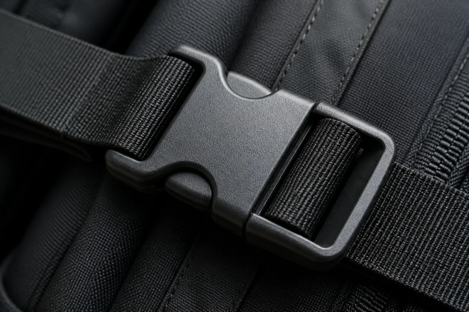
Side release buckle attached to a woven webbing strap on a backpack
The Buckle Assembly Table
Step
Requirement
Webbing width match
Exact match to the buckle
Webbing thickness
Within the buckle specification
Threading route
Correct path through the frame
Tail length
Sufficient for adjustment
Lock check
Test each assembled buckle
The Threading Table
Aspect
Requirement
Route
Per the specification drawing
Twist
None permitted
Fold direction
Correct face out
Tail finish
Cut and heat-sealed
Tightness
Firm without distortion
The Webbing Match Table
Buckle size
Webbing width
20 millimetre
20 millimetre
25 millimetre
25 millimetre
38 millimetre
38 millimetre
50 millimetre
50 millimetre
The Buckle Defect Table
Defect
Cause
Buckle slides under load
Webbing too thin for the buckle
Buckle will not grip
Wrong webbing type
Release under load
Wrong buckle class
Webbing bunches
Threading route error
Buckle cracks
Impact or material defect
Strap twists
Incorrect fold direction
The Load Class Table
Application
Buckle class
Main shoulder strap
High load
Sternum strap
Light load
Compression strap
Moderate load
Waist belt
High load
Accessory strap
Light load
Drawcord
Cord lock
The Adjustment Table
Function
Component
Length adjustment
Ladder lock or side release
Tension adjustment
Cam buckle
Quick release
Side release
Fixed loop
Sewn or riveted
Tooling and Workstation Setup
Hardware stations determine consistency. The tooling, the lighting, and the arrangement of components control the defect rate more than operator skill alone.
The Tooling Table
Tool
Use
Hand press
Moderate volume
Pneumatic press
Higher volume
Setting die set
Flare formation
Snap setter
Snap components
Eyelet setter
Eyelet components
Hole punch
Preparing the opening
Cutting punch
Clean edge preparation
The Die Maintenance Table
Check
Frequency
Die profile inspection
Per shift
Wear assessment
Weekly
Replacement
Per wear limit
Storage
Protected from damage
Record
Per die reference
The Workstation Table
Element
Requirement
Lighting
Direct, shadow-free
Component bins
Labelled by reference
Reference sample
Mounted at the station
Work instruction
Displayed
Defect bin
Available
Setting record
Kept at the station
The Force Control Table
Method
Consistency
Fixed press stop
High
Pressure regulated
Moderate to high
Manual hammer
Low
Operator judgement
Lowest
The Ergonomic Table
Factor
Consideration
Bench height
Press operation comfort
Repetition
Rotation of tasks
Grip force
Alternative tools
Hand protection
Sharp component edges
Noise
Press and hammer operations
The Training Table
Topic
Content
Component identification
Reference and pairing
Stack measurement
Correct method
Die selection
Match to hardware
Setting technique
Force and alignment
Inspection criteria
Accept and reject
Defect recording
Traceability
The Production Control Table
Control
Purpose
First article check
Confirms setup
In-process check
Detects drift
Die change record
Traceability
Component batch record
Traceability
Operator sign-off
Accountability
Factory note: The single most effective control at a hardware station is a mounted reference sample showing an acceptable joint and two rejected joints beside it. Operators compare against the physical reference rather than against a written description, and defects such as an undersized flare or a crushed fabric stack are caught within seconds of occurring.
Testing Hardware Joints
A hardware joint can only be verified by testing it. Visual inspection confirms the head is undamaged; it does not confirm that the flare is fully formed or that the buckle will hold its rated load.
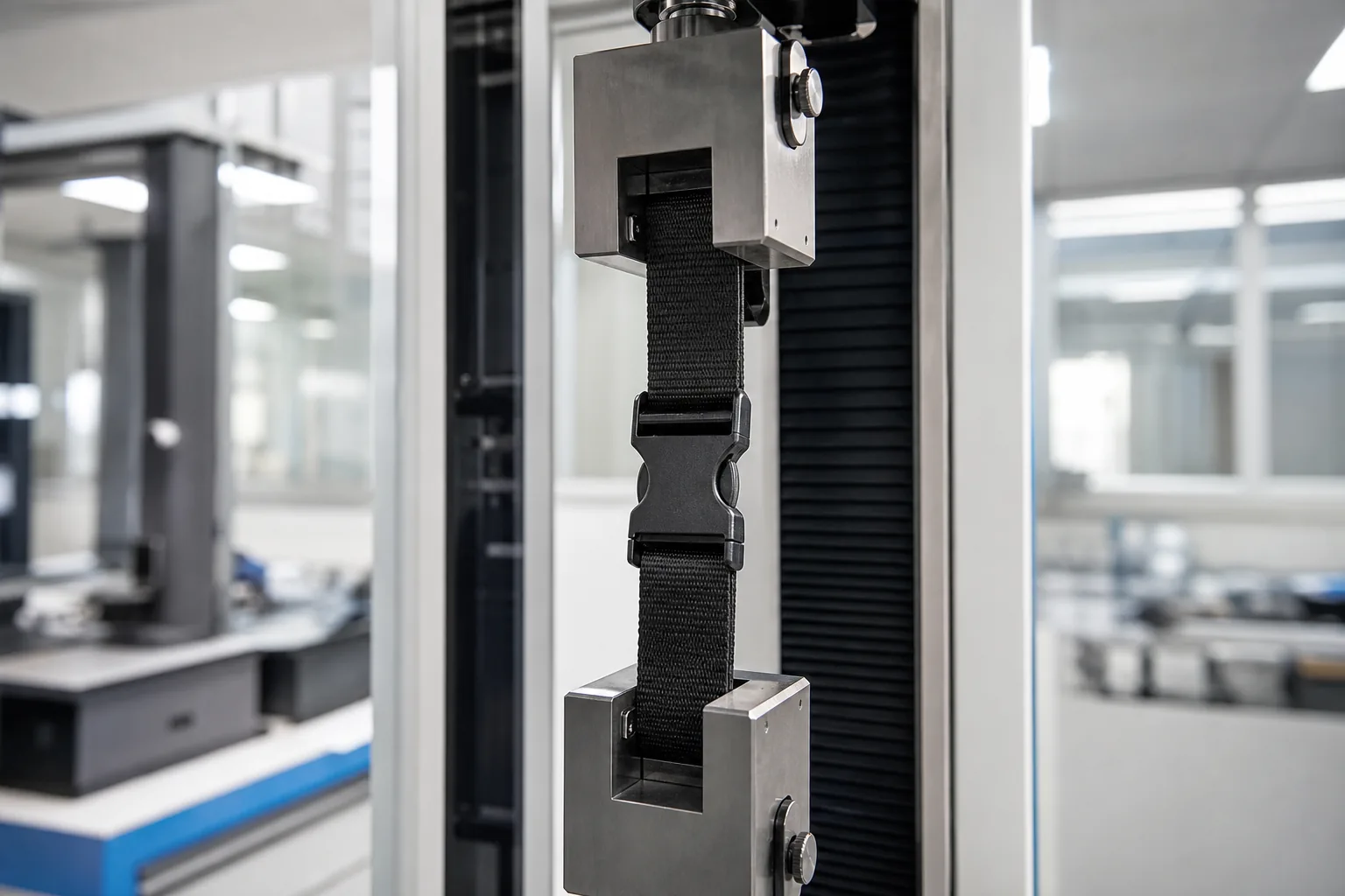
Tensile strength test on a plastic buckle and webbing in a quality control laboratory
The Test Methods Table
Test
Measures
Pull test
Joint strength
Retention test
Snap closing force
Cyclic load test
Fatigue resistance
Buckle load test
Rated capacity
Corrosion test
Finish durability
Impact test
Buckle cracking
Abrasion test
Webbing wear at the buckle
The Pull Test Table
Component
Test direction
Rivet in webbing
Axial pull
Rivet in fabric
Perpendicular pull
Eyelet
Axial pull
D-ring attachment
Perpendicular pull
Snap
Separation force
The Acceptance Table
Joint
Verification
Rivet
No movement under the rated load
Snap
Closes and holds per specification
Eyelet
No tearing or deformation
Buckle
Holds the rated load without release
D-ring
No deformation of the anchor
The Test Frequency Table
Test
Frequency
Pull test
First article and per batch
Snap retention
Per batch
Buckle load
Per hardware lot
Cyclic load
Per supplier qualification
Corrosion
Per finish specification
Impact
Per new component
The Sample Table
Sample type
Purpose
First article
Setup verification
Production sample
Batch confirmation
Retained reference
Comparison standard
Field return
Failure investigation
The Test Record Table
Field
Content
Date
Test date
Component reference
Hardware identification
Batch
Production batch
Result
Measured value
Limit
Acceptance criterion
Outcome
Pass or fail
Tester
Name
The Field Failure Table
Field symptom
Investigate
Rivet loosened
Flare formation and die wear
Fabric torn at the rivet
Reinforcement and force
Snap released in use
Component pairing and spring
Eyelet pulled out
Washer presence
Buckle cracked
Material class and impact
Strap slipped
Webbing and buckle match
Common Hardware Problems and Corrections
Most hardware problems repeat across factories because they originate in a small number of setup decisions.
The Problem Matrix
Symptom
Likely cause
Correction
Rivets loosen after use
Undersized flare
Correct die and force
Fabric crushed at the joint
Excessive force or short rivet
Recalculate rivet length
Rivet tears through
No reinforcement
Add interfacing or washer
Snaps hard to close
Wrong component pairing
Use matched sets
Snaps open easily
Weak spring
Change supplier lot
Eyelets tear out
Missing washer
Add washer and reinforcement
Buckles slip
Webbing too thin
Match webbing to buckle
Buckle releases under load
Wrong class
Specify a higher load class
Hardware corrodes
Inadequate plating
Confirm the finish specification
Strap twists
Wrong fold direction
Correct the threading instruction
The Root Cause Order Table
Step
Check
1
Confirm hardware matches the specification
2
Measure the material stack at the joint
3
Inspect the die for wear
4
Verify the press force setting
5
Check the reinforcement requirement
6
Test a sample joint to destruction
7
Compare with the retained reference
The Prevention Table
Control
Effect
Reference sample at the station
Immediate visual standard
Die inspection per shift
Catches wear early
Stack height verification
Correct rivet selection
Component pairing control
Prevents snap mismatch
Batch testing
Detects supplier variation
Work instruction
Consistent threading
The Corrective Action Table
Finding
Action
Isolated defect
Rework the unit
Batch defect
Contain and inspect the batch
Die wear
Replace and verify
Component defect
Escalate to the supplier
Specification gap
Revise the tech pack
Specifying Hardware in the Tech Pack
Hardware specification has to be explicit. Hardware is the component group most often described by appearance rather than by measurable properties.
The Required Fields Table
Field
Example
Component type
Tubular rivet
Material
Brass
Finish
Plated, colour reference
Dimensions
Diameter and length
Load requirement
Minimum pull strength
Reinforcement
Interfacing plus washer
Webbing match
Width and thickness
Setting method
Hand press with die reference
Test requirement
Pull test per batch
The Weak Specification Table
Weak
Strong
Metal rivet
Brass tubular rivet, 8 mm, plated
Strong buckle
Side release buckle rated to a stated load
Silver snap
Ring snap, brass, colour reference
Use a washer
Metal washer, 12 mm, at all load points
Good quality
Pull test at a stated load per batch
The Drawing Table
Element
Requirement
Hardware position
Dimensioned on the drawing
Stack indication
Layers shown at each joint
Reinforcement
Shown and dimensioned
Threading route
Diagram provided
Edge distances
Stated
The BOM Table
Column
Content
Reference
Unique code
Description
Component and finish
Supplier
Approved source
Dimensions
Size specification
Quantity
Per unit
Testing
Required test
The Approval Table
Stage
Check
Component approval
Sample and test report
First article
Joint and buckling check
Production pilot
Batch consistency
Change control
Written approval for substitution
Cost and Sourcing Considerations
Hardware is a low-value, high-consequence component group. Substituting it to save a small amount per unit is the classic route to a field failure.
The Cost Structure Table
Element
Character
Component cost
Per piece
Setting labour
Per operation
Tooling
Die and press
Testing
Per batch
Warranty risk
Field failure
The Cost Comparison Table
Hardware choice
Relative cost
Steel plated rivet
Lowest
Brass rivet
Low
Stainless rivet
Moderate
Standard plastic buckle
Low
High-load buckle
Moderate
Metal buckle
Higher
The Substitution Risk Table
Substitution
Risk
Lower-grade plating
Corrosion
Thinner webbing
Buckle slip
Lower load class buckle
Release under load
Different rivet length
Poor flare
Different snap set
Mismatch
The Supplier Control Table
Control
Practice
Approved supplier list
Named sources only
Incoming inspection
Per batch sampling
Test reports
Retained on file
Change notification
Required in writing
Traceability
Batch records kept
The Volume Table
Volume
Sourcing approach
Prototype
Sample quantities from the approved source
Small run
Standard packaging quantities
Repeat program
Consignment or scheduled delivery
Large program
Direct arrangement with the component maker
Factory note: A hardware substitution that saves a few cents per unit can cost more than the entire saving in a single warranty claim, once the claim, the freight, the replacement unit, and the customer relationship are counted. Where a substitution is unavoidable, it should be tested to the same pull and retention criteria as the original before it goes into production, and the change should be recorded against the style.
Managing Hardware Assembly on the Line
Hardware operations are short, repetitive, and easy to underestimate when planning capacity. They also sit on the critical path for several operations that follow them.
The Line Position Table
Sequence
Operation
1
Panel preparation and reinforcement
2
Punching or cutting openings
3
Hardware setting
4
In-process inspection
5
Assembly of panels
6
Final inspection
The Capacity Table
Factor
Influence
Operations per unit
Total hardware count
Cycle time per operation
Press and handling time
Setup time
Die changes
Rework time
Defect rate
Station count
Layout decision
The Bottleneck Table
Situation
Effect
Single press for many styles
Queue and waiting
Frequent die changes
Lost time
Manual hammer operations
Slower and variable
Inspection after every unit
Slower throughput
The Batching Table
Approach
Character
By style
Fewer die changes
By hardware type
Efficient within a run
By operation
Specialist stations
Single piece flow
Simple tracking, more changes
The Traceability Table
Record
Content
Hardware batch
Component lot
Die reference
Which die was used
Press setting
Force parameter
Operator
Who set the hardware
Date and shift
Production period
Test result
Pull and retention check
The Throughput Table
Volume
Station arrangement
Prototype
One station, manual
Small batch
One station per operation type
Medium run
Dedicated hardware area
Large run
Automated feed where justified
The Rework Table
Defect
Rework feasibility
Loose rivet
Remove and replace, material may be marked
Crushed material
Usually not recoverable
Wrong snap component
Replace, fabric may be marked
Bad eyelet
Replace with a larger washer
Wrong buckle
Replace, straightforward
Corroded hardware
Replace before shipment
The Process Control Table
Control point
Action
Setup
First article verification
During production
Periodic pull check
On die change
Re-verify the first article
On hardware batch change
Verify the new batch
End of run
Confirm the record is complete
The Documentation Table
Document
Purpose
Work instruction
Method
Reference sample
Visual standard
Test record
Verification
Die record
Tooling traceability
Batch record
Component traceability
The Hardware Assembly Checklist
Specification
Item
Done
Component type stated
☐
Material and finish stated
☐
Dimensions stated
☐
Load requirement stated
☐
Reinforcement specified
☐
Webbing match specified
☐
Setting method specified
☐
Test requirement specified
☐
Preparation
Item
Done
Approved supplier confirmed
☐
Incoming inspection completed
☐
Stack height measured at each joint
☐
Die selected and inspected
☐
Press force verified
☐
Reference sample mounted at the station
☐
Work instruction displayed
☐
Production
Item
Done
First article approved
☐
Pull and retention checks performed
☐
Die wear monitored
☐
Defects recorded and contained
☐
Batch records completed
☐
Final
Item
Done
All hardware present and correct
☐
Threading routes correct, no twist
☐
Flares formed and heads undamaged
☐
Buckles operate and hold
☐
Snaps close and retain
☐
Retained sample stored
☐
The Eight Rules
Rule
Reason
Measure the stack before selecting the rivet
Determines flare
Inspect the die every shift
Wear causes loose joints
Mount a reference sample at the station
Fastest defect detection
Reinforce every load-bearing joint
Prevents tear-out
Match webbing exactly to the buckle
Prevents slipping
Test the first article and per batch
Confirms setup and supply
Record the hardware batch and die
Enables investigation
Approve substitutions in writing after testing
Prevents field failure
FAQ
Why do rivets come loose after a few months even though they passed the in-house pull test?
The usual cause is an undersized flare that grips the material initially but relaxes as the joint cycles. This happens when the rivet is too long for the stack, when the die is worn, or when the press force is set low. Because the joint holds at the moment of testing, the defect passes inspection and only appears in the field. Monitoring die wear per shift and verifying the stack height before selecting the rivet both prevent it.
How do I know which rivet length to use?
Select the rivet length from the measured stack height at the joint, not from the material combination in general. The correct length is the measured stack plus the flare allowance specified by the rivet supplier. Where the stack varies across a panel, measure at the thickest point at that specific joint, or specify a longer rivet where the variation exceeds the allowance.
What is the difference between a tubular rivet and a solid rivet?
A tubular rivet has a hollow end that rolls outward to form the flare, which makes it suitable for fabric and webbing joints where the material should not be crushed. A solid rivet is deformed across its whole shank and produces a stronger permanent joint, but it requires higher force and is generally used in rigid assemblies rather than in soft materials.
Why does a snap fastener sometimes refuse to close?
Almost always because the socket and stud come from different component sets, or from different manufacturers, and the engagement dimensions do not match. Snap components should be purchased as matched sets from a single source and kept paired through production. Fabric thickness outside the component specification can also prevent closing, because the post length becomes insufficient to seat the two halves.
How do I stop a buckle from slipping under load?
Match the webbing thickness to the buckle specification. Slipping occurs when the webbing is thinner than the buckle’s gripping geometry expects, so the teeth or cam cannot bite. The webbing width must match the buckle size exactly, and the thickness must fall within the range the buckle is designed for. Switching to a thicker webbing or to a cam buckle designed for adjustment under load resolves the majority of cases.
Should every hardware joint have a washer?
Every load-bearing joint should have either a washer or a reinforcement patch, because these spread the load over a larger area and prevent the hardware from tearing through soft material. Light-duty joints in stable material, such as a cord lock on a drawcord, do not need one. The specification should state which joints are load-bearing so the requirement is not left to operator judgement.
Why does fabric tear around a rivet even when the rivet is set correctly?
Because the joint lacks reinforcement or sits too close to the material edge. A correctly set rivet concentrates the load at its head and flare, and an unreinforced fabric fails at that point before the rivet does. Adding an interfacing patch, a webbing tab, or a washer distributes the load, and the edge distance on the drawing should keep the joint away from the material edge.
How often should setting dies be inspected?
Inspect the die profile at the start of every shift, assess wear weekly against the manufacturer’s wear limit, and replace it when the limit is reached. Die wear is gradual and shows up first as an inconsistent flare between joints rather than as a clear defect. A quick comparison of consecutive joints against the station reference sample catches wear well before it produces a field failure.
Can a cheaper buckle be substituted to reduce unit cost?
Only against the same load requirement. A lower load class or a different material may hold in a static test and still fail under impact or cyclic loading, which are the conditions that cause buckles to crack in use. Any substitution should be tested to the original pull and impact criteria, approved in writing, and recorded against the style, because the saving per unit is small compared with the cost of a single warranty claim.
Conclusion
Hardware assembly is where a backpack is either locked together properly or quietly prepared for failure. The components themselves are inexpensive and the operations are brief, which is exactly why they receive less attention than they need.
The discipline has four parts. Specify hardware by measurable properties rather than by appearance, including material, finish, dimensions, load requirement, and the reinforcement that surrounds each joint.
Select the rivet from the measured stack height and inspect the setting die every shift, because that is where loose joints originate. Mount a physical reference sample at every hardware station, so a defective flare or a crushed stack is recognised within seconds. And test the joints on the first article and on each production batch rather than relying on visual inspection, which cannot see inside a joint.
For factories, hardware competence shows up as a lower warranty rate on exactly the failures that are most visible to a customer: a strap that came away, a buckle that broke, a snap that stopped closing.
For buyers, the two specification additions worth making today are a minimum load requirement for every load-bearing hardware item and a stated reinforcement at every joint. Neither adds cost, both give the line a measurable acceptance criterion, and together they remove the most common source of hardware complaints before the goods leave the factory.