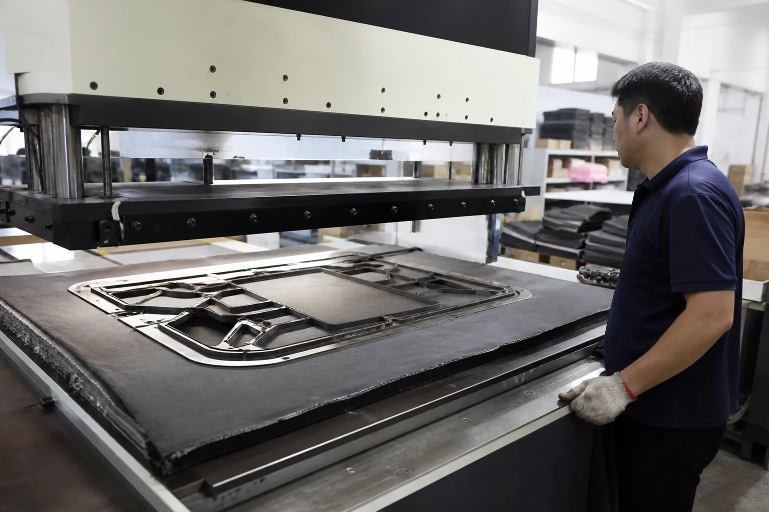
Cutting Dies and Moulds: Asset Control in Factories
Cutting Dies and Moulds: Asset Control in Factories
A cutting die is the object that turns a paper pattern into thousands of identical fabric panels. It is the point at which the designer’s intent becomes the factory’s physical output, and every panel that leaves the cutting table carries its geometry. When a die is worn, damaged, or swapped without record, the defect appears much later, in a bag that does not match its approved sample.
Most factories treat dies as consumable tooling rather than as assets. They are bought when an order arrives, stored somewhere on a shelf, repaired when they break, and forgotten between seasons. The cost of that neglect is not the replacement price of a die. It is the panel that drifts, the sample that no longer matches production, and the customer who finds that a reorder does not look like the original.
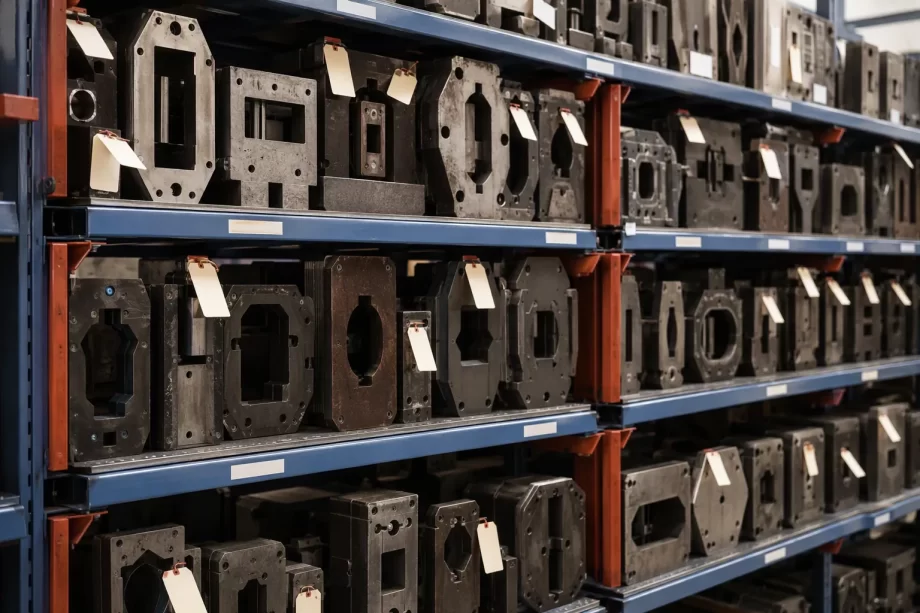
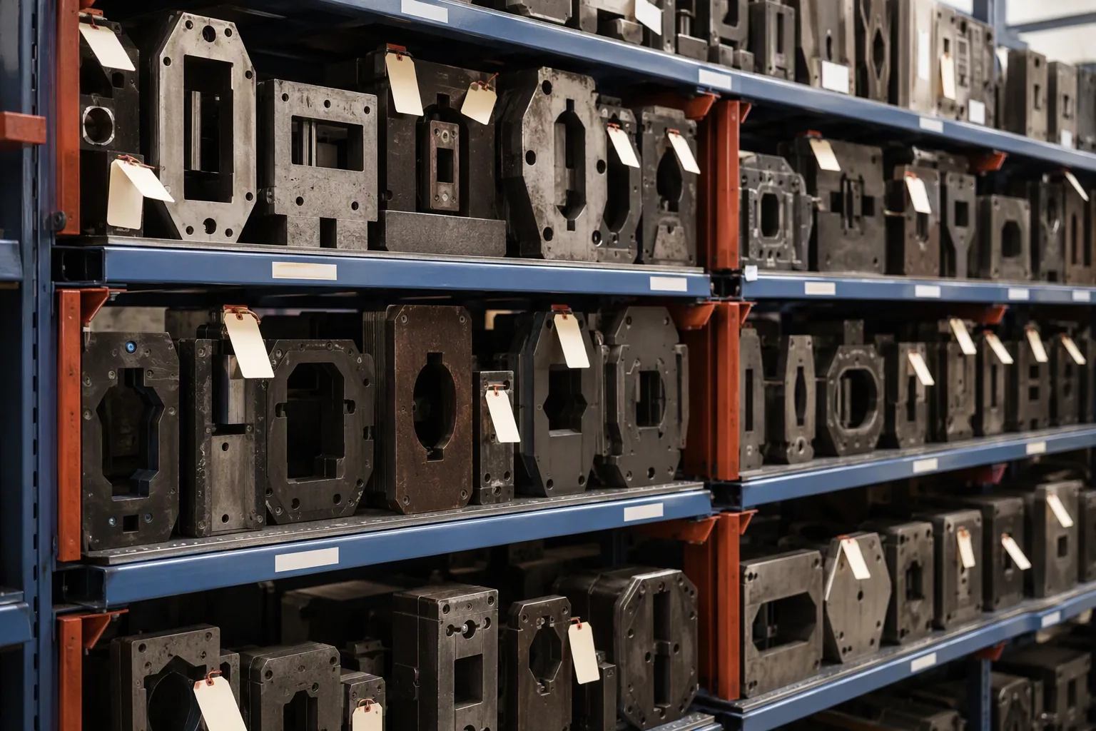
Steel cutting dies stored on a numbered rack in a tooling store
This guide covers die and mould control from the manufacturer’s perspective: what tooling a bag factory holds, how dies and moulds are developed and approved, how they are identified and stored, how usage and wear are tracked, how maintenance and repair are managed, how ownership and custody work, how tooling cost is recovered, and how dies are disposed of or returned at the end of a program.
A die that cuts a backpack side panel may run for tens of thousands of impressions across several seasons. Its geometry determines the fit of every other panel, the position of every stitch line, and the alignment of every piece of hardware. A die that has drifted by two millimetres produces a bag that assembles badly, even though every other process is correct.
The Asset Table
Characteristic
Implication
Long service life
Requires maintenance, not replacement
Geometry critical
Wear has quality consequences
Program specific
Value tied to the SKU
Reusable across orders
Value persists between seasons
Costly to remake
Lead time and expense at risk
Shared across buyers
Custody and ownership must be clear
The Neglect Cost Table
Neglect
Consequence
No identification
Wrong die used
No storage discipline
Physical damage
No usage record
Wear discovered late
No maintenance
Progressive geometry drift
No ownership record
Dispute at program end
No disposal process
Obsolete dies occupy space
The Tooling Inventory Table
Item
Function
Steel rule cutting die
Panel cutting
Clicker die
Small component cutting
Perforating die
Ventilation and detail
Embossing die
Logo and texture
Hot stamping die
Foil marking
Injection mould
Plastic hardware
Compression mould
Foam and padding
Sewing jig
Stitch path guide
The Lifecycle Table
Stage
Activity
Development
Drawing, making, trialling
Approval
Sample sign-off
Production
Periodic use
Maintenance
Scheduled and reactive
Storage
Between programs
Retirement
Disposal or return
The Consequence Table
Control gap
Failure mode
No unique identifier
Die confusion
No reference panel
Wear undetectable
No issue log
Usage invisible
No condition check
Failure in production
No ownership register
Custody dispute
Factory note: The cheapest control in the whole system is a unique number stamped on the die and a first-article panel kept with it. Together they make it possible to answer the only two questions that matter when a dimensional problem appears: which die cut this panel, and what did the panel look like when the die was new?
Types of Tooling in a Bag Factory
Bag production uses several categories of tooling. Each has a different cost, a different maintenance need, and a different ownership reality.
The Cutting Tool Table
Tool
Used for
Steel rule die
Main panels, single layer
Progressive die
Multiple cuts in sequence
Clicker die
Small leather or fabric parts
Strip die
Webbing and binding
Punch die
Holes and slots
The Forming Tool Table
Tool
Used for
Hot stamping die
Foil logos on leather
Embossing plate
Texture and pattern
Heat press plate
Seam sealing
Ultrasonic horn
Welded joints
Welding jig
Aligned bonding
The Mould Table
Mould
Used for
Injection mould
Buckles, adjusters, hooks
Compression mould
EVA and foam components
Blow mould
Hollow plastic parts
Rotational mould
Large hollow forms
The Jig and Fixture Table
Fixture
Function
Sewing jig
Consistent stitch path
Pocket template
Pocket placement
Zipper guide
Straight zipper insertion
Assembly fixture
Component alignment
Rivet jig
Hardware spacing
The Specification Table
Parameter
Typical consideration
Steel rule thickness
Material and cut depth
Rule hardness
Tool life against cost
Cutting board compatibility
Scoring and life
Die board material
Stability under pressure
Ejection material
Clean release
The Cost Table
Tooling
Relative cost
Steel rule die
Low to moderate
Clicker die
Low
Hot stamping die
Moderate
Injection mould
High
Compression mould
Moderate
Assembly fixture
Low
Developing and Approving Tooling
A die is made from a drawing. If the drawing is wrong, the die is wrong, and every panel produced from it is wrong. Approval is therefore a dimensional exercise, not a paperwork formality.
The Development Step Table
Step
Activity
1
Finalise the pattern and specifications
2
Prepare the die drawing
3
Select the die maker
4
Manufacture the die
5
Trial cut the first panel
6
Measure against the specification
7
Approve or rectify
The Drawing Table
Element
Content
Panel outline
Full geometry with tolerances
Grain direction
Marked orientation
Notches
Position and size
Hole positions
Coordinates and diameter
Identification
Part number and revision
The Approval Table
Check
Requirement
Overall dimensions
Within tolerance
Notch positions
Within tolerance
Hole positions
Within tolerance
Corner radii
As specified
Grain alignment
Correct orientation
Edge quality
Clean, no crushing
The Trial Table
Trial
Purpose
First article cut
Geometry verification
Multiple layer cut
Stack behaviour
Production material trial
Actual fabric response
Assembly trial
Fit with other panels
Wear trial
Initial durability
The Tolerance Table
Parameter
Typical approach
Length and width
Tight on fitting edges
Notch position
Tight, assembly depends on it
Hole position
Tight for hardware fit
Corner radius
Moderate
Overall symmetry
Tight for paired panels
The Rectification Table
Defect
Action
Dimension outside tolerance
Remake or adjust
Notch misplaced
Remake
Poor edge quality
Adjust rule or board
Incorrect grain marking
Correct the instruction
Assembly misfit
Recheck the pattern
The Approval Record Table
Field
Purpose
Die identifier
Traceability
Revision
Change control
Approval date
Chronology
Approver
Accountability
Reference panel
Physical standard
Rectifications
History
Identification and Storage
A die without a number is an anonymous object. Identification is what makes every other control possible: usage records, condition checks, and ownership all depend on being able to say which die is which.
The Identification Table
Method
Character
Stamped number
Permanent on the die board
Engraved part number
Permanent, precise
Colour code
Quick visual grouping
Label with barcode
Machine readable
Storage location code
Physical traceability
The Identifier Structure Table
Component
Meaning
Customer code
Whose program
Style code
Which bag model
Part code
Which panel
Revision letter
Which version
Sequence
Which die of a set
The Storage Table
Requirement
Reason
Vertical rack for flat dies
Prevents warping
Numbered positions
Retrieval without search
Climate control
Prevents rust and board swell
Protection from impact
Preserves geometry
Segregation by program
Prevents mix-ups
Restricted access
Accountable custody
The Location Register Table
Field
Content
Die identifier
Unique number
Storage position
Rack and slot
Program
Customer and style
Status
Active, spare, obsolete
Last used
Date
Custodian
Responsible person
The Storage Failure Table
Failure
Consequence
Dies stacked flat
Warping under load
Damp store
Rust on rules
Unlabelled shelf
Wrong die retrieved
Open access
Loss and damage
Mixed programs
Confusion at issue
The Retrieval Table
Step
Control
1
Request raised against the work order
2
Register checked for location
3
Die withdrawn and inspected
4
Issue recorded with the operator
5
Return and inspection after use
Factory note: Storage is where most die damage happens, not production. A die that is laid flat under other dies, or kept in a damp corner, will be out of tolerance before its first cut of the season. Vertical storage in a dry, numbered rack costs very little and removes an entire class of dimensional complaint.
Usage and Wear Tracking
Dies wear gradually. The geometry changes slowly enough that nobody notices from one order to the next, and the problem appears only when a panel no longer assembles with the panel beside it.
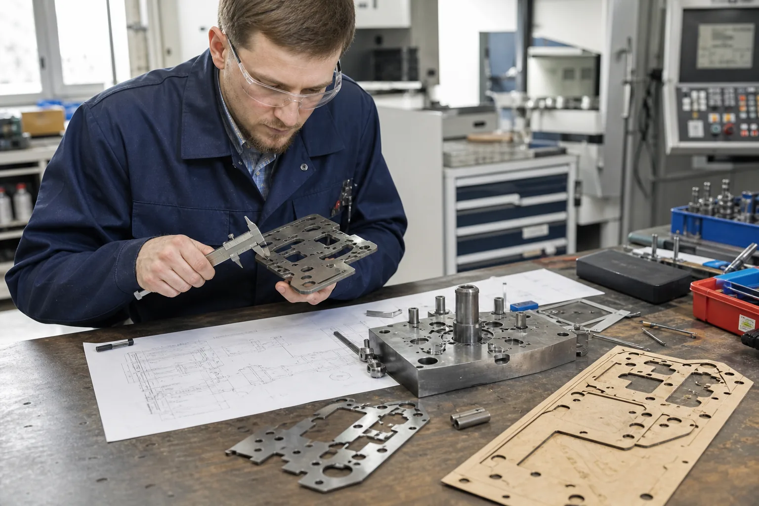
Technician inspecting a steel rule die with callipers
The Usage Record Table
Field
Purpose
Die identifier
Traceability
Work order
Which production run
Operator
Responsibility
Material cut
Abrasiveness
Quantity cut
Cumulative wear
Condition on return
Early detection
The Wear Mechanism Table
Mechanism
Effect
Rule edge rounding
Crushed or frayed edges
Rule compression
Reduced cutting depth
Board swell
Geometry change
Rule loosening
Displacement
Ejection failure
Panel retention
The Inspection Table
Interval
Check
At issue
Visual and identification
During long runs
Periodic panel check
At return
Condition and clean
Monthly
Full geometry against the standard
After repair
Re-verification
The Measurement Table
Measurement
Method
Overall dimensions
Against the reference panel
Notch position
Coordinate measurement
Hole position
Gauge or template
Rule height
Depth gauge
Board flatness
Straight edge
The Threshold Table
Condition
Action
Within tolerance
Continue use
Minor deviation
Monitor closely
Approaching limit
Plan replacement
Out of tolerance
Remove from service
Damaged
Repair or replace
The Trend Table
Signal
Interpretation
Gradual dimension drift
Normal wear
Sudden geometry change
Damage or displacement
Rising edge defects
Rule edge failure
Assembly complaints rising
Die drift across a set
Maintenance and Repair
Maintenance restores geometry; repair restores function. Both need records, because the history of a die is what justifies continuing to use it or replacing it.
The Maintenance Table
Activity
Frequency
Cleaning
After each use
Rust prevention
After cleaning
Rule inspection
Each issue
Board flatness check
Monthly
Geometry verification
Periodic or post-repair
Full service
Annual or by volume
The Repair Table
Fault
Repair
Blunt rule
Re-sharpen or replace rule
Displaced rule
Reset and secure
Swollen board
Replace board
Damaged notch
Repair or remake
Loose ejection
Replace material
Warped die
Straighten or remake
The Repair Decision Table
Situation
Decision
Minor cosmetic wear
Continue, monitor
Geometry near limit
Repair
Repair cost below replacement
Repair
Repair cost above replacement
Remake
Die obsolete
Retire
The Verification After Repair Table
Check
Requirement
Dimensions
Back within tolerance
Notch and hole position
Confirmed
Edge quality
Clean cut restored
Assembly fit
Trial with mating panels
Record updated
Repair logged
The Record Table
Field
Purpose
Die identifier
Traceability
Maintenance date
Chronology
Work performed
History
Parts replaced
Cost tracking
Verified by
Accountability
Result
Return to service or retire
The Continuity Table
Risk
Mitigation
Critical die fails mid-order
Duplicate die held
Die maker unavailable
Multiple approved makers
Long replacement lead time
Replacement planned ahead
Spare rule, board, and fasteners
Wear items in stock
Ownership and Custody
Tooling ownership is one of the most common sources of friction at the end of a program. The die was paid for by someone, it was made to someone’s drawing, and it physically sits in the factory. Those three facts do not automatically agree.
The Ownership Table
Arrangement
Who owns the tooling
Buyer-funded, buyer drawing
Buyer
Buyer-funded, factory drawing
Per contract
Factory-funded, buyer-specific
Usually factory, but restricted
Factory-funded, generic
Factory
Jointly funded
Per written agreement
The Custody Table
Situation
Factory obligation
Buyer-owned tooling held in plant
Care and preservation
Buyer-owned, in use
Use only for the buyer’s orders
Buyer-owned, idle
Maintain, do not dispose
Loan of tooling
Documented condition on receipt
Transfer to another factory
Written authorisation
The Register Table
Field
Purpose
Tooling identifier
Identification
Owner
Rights
Funding source
Cost history
Program
Association
Custody location
Physical control
Condition
Asset state
The Agreement Table
Clause
Content
Ownership
Who holds title
Use restriction
Whose orders it may serve
Custody
Who holds it and where
Maintenance
Who pays and who performs
Access
Inspection rights
Return
Conditions and timing
Replacement
If lost or damaged
The Dispute Table
Dispute
Root cause
Buyer claims tooling, factory refuses
No written ownership
Factory used tooling for another buyer
No use restriction
Buyer claims tooling was damaged
No condition record
Tooling not returned
No return clause
Tooling scrapped prematurely
No disposal authorisation
The Buyer-Owned Control Table
Control
Purpose
Inventory certificate
Confirms existence
Photographic record
Confirms condition
Periodic confirmation
Confirms continued custody
Restricted use commitment
Protects exclusivity
Return clause
Enables transfer
The Exclusivity Table
Situation
Requirement
Buyer-specific design
Tooling used only for that buyer
Generic component
Shared use acceptable
Buyer-branded hardware
Segregated and controlled
Embossing or logo die
Strictly segregated
Tooling Cost and Amortisation
Tooling is a real cost that must be recovered. How it is charged changes the buyer’s unit economics, the factory’s cash position, and what happens if the program ends early.
The Cost Element Table
Element
Character
Die drawing
Engineering time
Die manufacture
Tooling supplier invoice
Trial cutting
Material and labour
Approval process
Time and sampling
Modification
Additional engineering
Maintenance
Ongoing labour
Replacement
Periodic renewal
The Recovery Model Table
Model
Character
Separate tooling charge
Paid once, at start
Amortised into unit price
Spread across volume
Partly separate, partly amortised
Split approach
Factory investment
Recovered through margin
Buyer-financed, buyer-owned
Buyer assets
The Amortisation Table
Factor
Effect
Expected order quantity
Higher volume, lower unit share
Tooling life
Longer life, lower unit share
Program duration
Longer program, more recovery
Price sensitivity
Influences the chosen model
Program certainty
Forecasting risk
The Comparison Table
Model
Buyer consequence
Factory consequence
Separate charge
Immediate cash outlay
Immediate recovery
Amortised
Lower up-front cost
Recovery tied to volume
Split model
Balanced
Balanced
Factory investment
No tooling cost
Needs volume certainty
Buyer-owned
Asset on buyer’s books
Custody obligation
The Early Termination Table
Situation
Consequence
Program ends before recovery
Factory carries the shortfall
Buyer cancels after tooling made
Tooling charge may fall due
Volume falls short of forecast
Amortisation miss
Tooling returned to buyer
Recovery stops
The Quotation Table
Line item
Content
Tooling charge
Separate, one-off
Tooling amortisation
Per unit
Sample charge
Pre-production
Modification policy
Who pays for changes
Maintenance responsibility
Buyer or factory
The Financial Control Table
Control
Purpose
Tooling budget approval
Cost control
Invoice verification
Against the quotation
Amortisation tracking
Volume against forecast
Recovery monitoring
Program profitability
Disposal write-off
Asset cleanup
Change Control and Version Management
A design change almost always touches tooling. If the change is not controlled, two versions of a die exist, and panels from each end up in the same shipment.
The Change Trigger Table
Trigger
Tooling effect
Dimension change
Die modification or remake
Notch or hole move
Die modification
Material change
Rule or ejection adjustment
Construction change
New die or fixture
Hardware change
Mould or jig change
The Version Table
Element
Control
Revision letter
Incremented at each change
Drawing revision
Matches the die revision
Reference panel
Updated with the die
Work instruction
Updated to the new revision
Old die
Withdrawn from service
The Change Step Table
Step
Action
1
Change request raised
2
Effect on tooling assessed
3
Cost and lead time agreed
4
Tooling modified or remade
5
First article verified
6
Documents updated
7
Old tooling withdrawn
The Transition Table
Risk
Control
Mixed panels from two revisions
Old die withdrawn immediately
Old reference panel still in use
Replace with the new panel
Work instruction not updated
Document control
Stock of old panels
Segregate and dispose
The Documentation Table
Document
Content
Tooling register
Identity and status
Change record
What changed and when
Approval record
Sign-off evidence
Reference panel register
Physical standard
Withdrawal record
Removal from service
The Traceability Table
Question
Record that answers it
Which die cut this panel?
Usage log
Which revision was it?
Version control
Who approved it?
Approval record
When was it maintained?
Maintenance log
Who owns it?
Ownership register
Retirement, Disposal and Return
Every die reaches an end. The question is whether it reaches that end through a decision or through neglect, and whether the exit is documented.
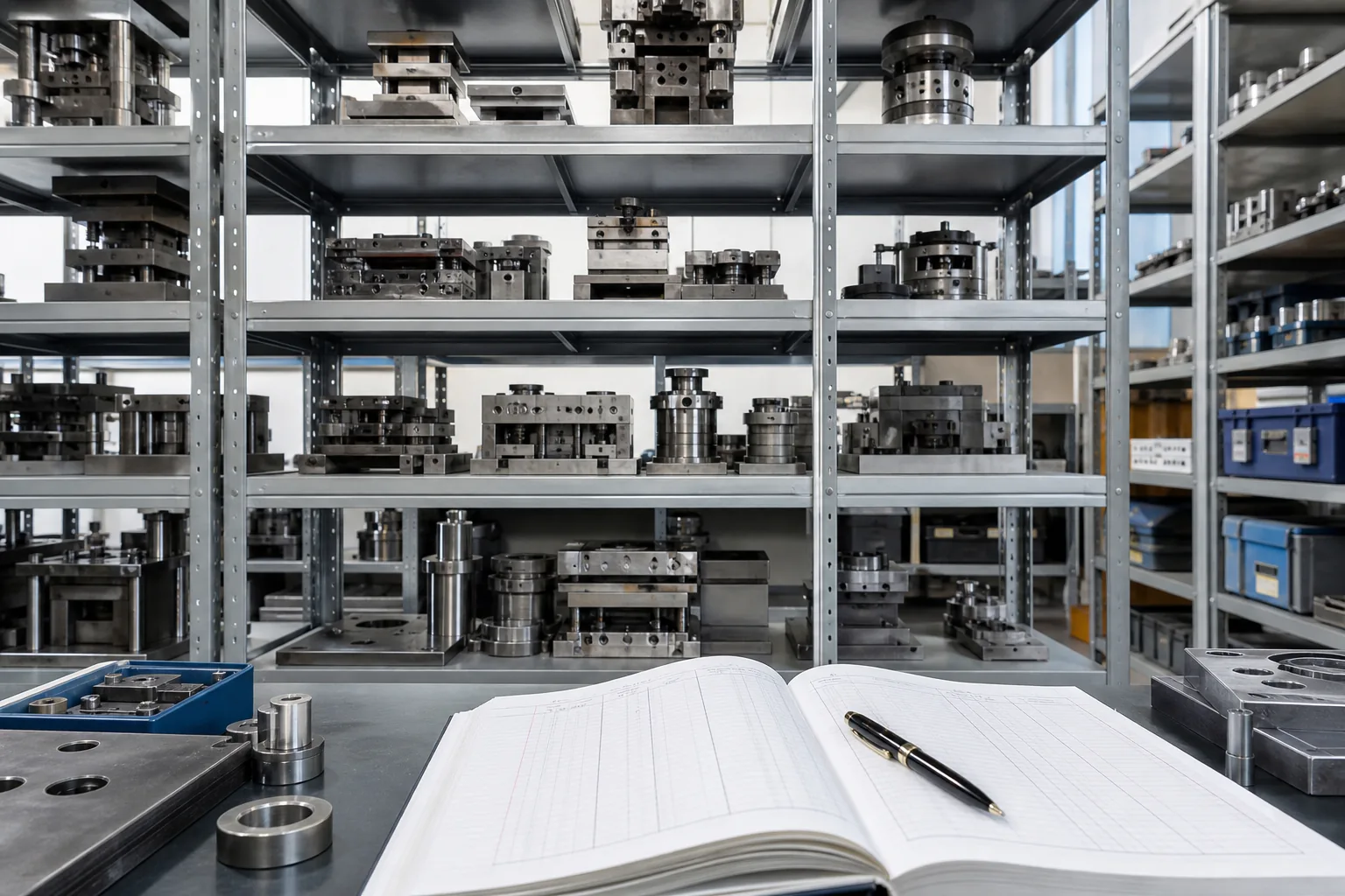
Factory tooling store with shelving, dies and an inventory ledger
The Retirement Trigger Table
Trigger
Condition
Program ended
No further orders expected
Out of tolerance
Beyond economic repair
Superseded by revision
Replaced by a new version
Customer request
Tooling returned or scrapped
Storage cost exceeds value
Idle for an extended period
Ownership expiry
Per the tooling agreement
The Disposal Decision Table
Situation
Action
Buyer-owned tooling
Return or scrap only on instruction
Factory-owned, reusable
Retain with capacity planning
Factory-owned, obsolete
Scrap with a record
Superseded revision
Withdraw and scrap
Confidential design
Scrap under controlled conditions
The Return Table
Step
Action
1
Written instruction from the owner
2
Condition assessment and record
3
Cleaning and protection
4
Packing to prevent damage
5
Dispatch with a consignment record
6
Owner acknowledgement
The Scrap Table
Control
Reason
Authorisation before scrapping
Prevents loss of buyer assets
Physical destruction of confidential tooling
Design protection
Record of destruction
Audit evidence
Removal from the register
Accurate inventory
Material recovery
Value where possible
The Record Closure Table
Field
Entry
Die identifier
The die being closed
Reason
Why it left service
Date
When
Method
Returned, scrapped, or retained
Authorised by
Accountability
Reference
Instruction or record number
Tooling Audits and Inventory Checks
An inventory that is only created once is a list of what used to exist. Periodic verification is what keeps the register and the shelf in agreement.
The Audit Scope Table
Scope
Content
Existence
Die physically present
Identification
Number matches the register
Condition
Usable, repairable, or scrap
Location
Actual position matches the record
Ownership
Owner recorded and correct
Documentation
Reference panel and drawing present
The Audit Frequency Table
Type
Frequency
Full inventory
Annually
Active tooling check
Quarterly
Pre-season check
Before each program start
Post-production check
At program end
Spot check
Random
The Discrepancy Table
Discrepancy
Action
Die missing
Investigate and correct the record
Unrecorded die found
Identify and register
Condition worse than recorded
Update and schedule repair
Owner unclear
Resolve before further use
Reference panel missing
Recreate and re-approve
The Reconciliation Table
Record
Compared with
Tooling register
Physical count
Usage log
Production records
Maintenance log
Repair invoices
Ownership register
Contracts and agreements
Location register
Rack positions
Manufacturer note: An audit that finds more discrepancies each year is not a failing audit; it is an audit that is finally being done properly. The purpose is not a clean sheet. The purpose is that the number stamped on a die, the panel kept beside it, and the line in the register all describe the same object, so that a quality problem can be traced to a cause instead of to a guess.
The Tooling Control Checklist
Die cutter pressing a steel rule die through fabric layers
Development and Approval
Item
Done
Pattern and specifications finalised
☐
Die drawing issued with tolerances
☐
Grain direction and notches marked
☐
Die manufactured to the drawing
☐
First article cut and measured
☐
Assembly trial completed
☐
Reference panel retained
☐
Approval recorded with revision
☐
Identification and Storage
Item
Done
Unique identifier stamped on the die
☐
Label with part name and program
☐
Storage position recorded
☐
Vertical rack storage in a dry area
☐
Segregation by program
☐
Restricted access with issue log
☐
Usage and Maintenance
Item
Done
Issue and return recorded
☐
Condition checked at each issue
☐
Periodic geometry verification
☐
Reference panel comparison
☐
Repair recorded with parts replaced
☐
Post-repair verification
☐
Replacement planning by volume
☐
Ownership and Change
Item
Done
Ownership recorded in the register
☐
Use restriction documented
☐
Custody and location recorded
☐
Maintenance responsibility agreed
☐
Change control with revision letters
☐
Superseded tooling withdrawn
☐
Disposal or return authorised
☐
The Eight Rules
Rule
Reason
Give every die a unique number
Nothing else works without identity
Keep a first-article panel with the die
Wear becomes visible
Store flat dies vertically and dry
Prevents warping and rust
Record issue and return
Usage is the basis of wear prediction
Verify geometry periodically
Drift is gradual and unnoticed
Write down who owns the tooling
Prevents the end-of-program dispute
Control revisions and withdraw old dies
Prevents mixed panels
Audit the register against the shelf
Keeps records and reality aligned
FAQ
How long does a steel rule cutting die last?
It depends on the rule grade, the material being cut, the number of layers per cut, and the cutting board condition, but a die cutting fabric in a normal production environment is expected to run through a substantial number of impressions before the rule edge needs attention. Abrasive materials, thick stacks, and poor board contact shorten that considerably. The practical answer is not to rely on a nominal figure but to measure: keep a first-article panel, check dimensions against it at planned intervals, and let the observed drift rather than a generic number decide when the die is serviced or replaced.
Who owns the cutting dies made for our orders?
It depends entirely on what the contract says, and that is the problem. If the buyer paid for the tooling and provided the drawing, the usual position is that the buyer owns it, held in the factory as custodian. If the factory funded the tooling and developed the design, ownership normally stays with the factory unless the agreement transfers it. Because the physical object sits inside the factory, ownership has to be recorded in writing at the point the tooling is ordered, not negotiated at the end of the program. The register should record owner, funding source, use restriction, and custody location.
What should be kept with each die?
A unique identifier stamped on the die, a label giving the part name, program, and revision, a first-article reference panel from the approved die, and a record of the drawing revision it was made to. Those four things make it possible to answer the questions that arise when a dimensional problem appears: which die cut the panel, when was it last verified, which revision was in force, and what the geometry looked like when the die was new. Without the reference panel, wear is undetectable until the panels stop assembling.
How should dies be stored?
Vertically on a numbered rack, in a dry area, positioned so that dies are not stacked under load and cannot be struck by passing traffic. Flat dies laid one on top of another deform over time, and dies kept in a damp store develop rust on the rules, which produces crushed or frayed panel edges. The rack should be numbered so that the location register and the shelf agree, and access should be controlled so that issue and return can be logged. Storage is the single largest source of avoidable die damage.
Should tooling cost be charged separately or amortised into the unit price?
Both models are used, and the choice is really a question of who carries the forecasting risk. A separate tooling charge recovers the cost immediately and is clean for the factory, but it is a visible up-front outlay for the buyer. Amortising into the unit price lowers the entry cost but leaves the factory exposed if the expected volume does not arrive, since the unrecovered balance disappears with the program. A split model, where part is charged separately and part amortised, is a common compromise. Whatever the model, the quotation should state the tooling charge, the amortisation, and who pays for modifications.
What happens to the tooling when a program ends?
It should be a decision, not drift. If the tooling is buyer-owned, the factory normally needs written instruction before doing anything with it, and the options are to retain it for a possible reorder, return it, or scrap it on the owner’s authorisation. If the tooling is factory-owned and the design is specific to that buyer, the factory should either retain it in anticipation of future orders or retire it formally. In all cases the register entry should be closed with the reason, date, method, and authorisation, so that the inventory reflects what actually exists.
How often should the tooling inventory be checked?
A full physical inventory once a year, a check of the active tooling before each production season, and a condition check of the tooling actually being used at the end of each program. Spot checks between those dates catch the drift that accumulates when a die is moved without updating the register. The check should cover existence, identification, condition, location, ownership, and whether the drawing and reference panel are present. A discrepancy is not a failure; it is the signal that the register needs correcting.
How do we handle a design change that affects the tooling?
Treat it as a controlled change with a revision increment. The change request goes to an assessment of the effect on each affected die, mould, or fixture, and the cost and lead time are agreed before work starts. The tooling is then modified or remade, a first article is cut and measured, the drawings, work instruction, and reference panel are updated to the new revision, and the superseded tooling is physically withdrawn from service. The withdrawal step matters most: leaving an old die available is the fastest route to having two revisions of panels in the same shipment.
What is the biggest tooling risk in a bag factory?
Mixed revisions and unidentified dies. Both produce the same symptom, which is a bag that does not match the approved sample even though every individual process appears correct. They are also the two failures that are hardest to trace once the panels have left the cutting table, because by then there is no way to know which die produced which panel unless the usage log and the identifier were maintained. Identification and revision control are cheap to set up and they remove most of the diagnostic work from every subsequent quality investigation.
Conclusion
Cutting dies and moulds are the physical memory of a design. They hold the geometry that the sample was approved against, and they carry it forward into every panel the factory produces. That makes them assets with a quality consequence, not consumables to be bought, stored, and forgotten.
The controls that protect them are unglamorous and inexpensive. Give every die a unique number and keep a first-article panel with it, so that wear becomes visible rather than theoretical. Store flat dies vertically in a dry, numbered rack, and log every issue and return. Verify geometry at planned intervals instead of waiting for an assembly complaint, and record repairs with the parts replaced.
Write down who owns the tooling before it is ordered, along with the use restriction and the custody obligation, because the alternative is a dispute at the end of the program. Control revisions so that only one version of a die is live at a time, and withdraw the superseded tooling physically rather than leaving it on the shelf. Close the register entry properly when a die leaves service, and check the register against the shelf at least once a year.
For factories, this is what makes an existing program repeatable and a reorder safe. A plant that can produce a panel identical to the approved sample two seasons later, and prove it with a reference panel and a record, is a plant a buyer can build a long product range on.
For buyers, the practical test is simple: ask to see the die number stamped on the tooling that cuts a panel, ask for the first-article panel kept with it, and ask the last date its geometry was verified.
If the factory can answer all three from a record rather than from memory, the tooling is under control. If it cannot, the sample approval means less than it appears to, because nothing in the chain between the approved sample and the next shipment is being held to a measured standard.