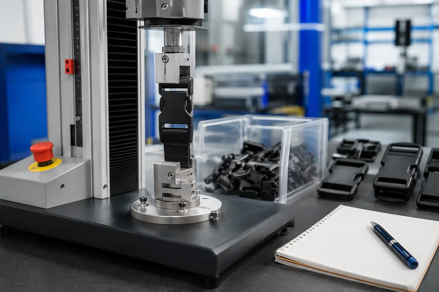
Injection-Moulded Components for Backpack Hardware
Injection-Moulded Components for Backpack Hardware
Buckles, adjusters, cord locks, and hooks are the smallest parts on a backpack and the ones most likely to end the product’s life. A strap that will not hold tension, a buckle that cracks in cold weather, or a ladder lock that slips under load turns an otherwise sound bag into a return.
None of these failures come from the fabric, the stitching, or the factory’s assembly skill. They come from a moulded part that was specified by appearance rather than by function.
Injection moulding is how nearly all of that hardware is made. Plastic pellets are heated until they flow, pushed into a steel cavity under pressure, and cooled into the finished shape. The process is fast, repeatable, and inexpensive at volume, which is exactly why it is used for the hundreds of small components that make a bag adjustable.
It is also unforgiving: the material, the mould, and the process parameters together decide whether a buckle survives a field season or fails in a cold warehouse.
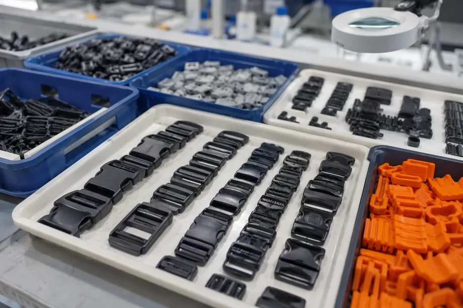
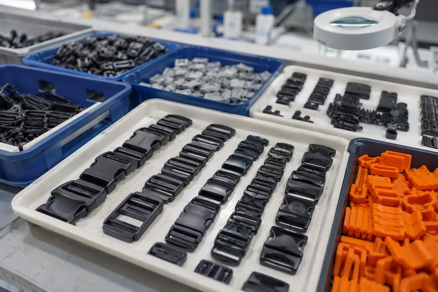
Moulded plastic buckles and adjusters sorted in trays
This guide covers moulded hardware from the manufacturer’s and buyer’s perspective: why small parts carry disproportionate risk, how moulding materials are selected, which components a backpack uses, how a mould is developed and approved, how process parameters affect quality, how moulded parts are inspected and tested, how tolerance and fit are controlled, how cost is structured, and how quality problems are contained when they appear.
Why Small Moulded Parts Carry Disproportionate Risk
A moulded buckle costs a fraction of a cent to a few cents. Its failure, however, is not measured in replacement cost. It is measured in the value of the returned bag, the cost of the customer complaint, and the possibility that an entire production run has to be sorted or recalled.
The Risk Table
Failure
Consequence
Buckle cracks
Bag unusable under load
Adjuster slips
Strap loses tension
Cord lock releases
Contents exposed
Hook deforms
Attachment fails
Material embrittles in cold
Field failure in winter
UV degradation
Cracking after sun exposure
The Cost Ratio Table
Measure
Relative scale
Part cost
Very low
Assembly cost
Low
Bag value
High
Return handling
High
Brand damage
Very high
The Failure Origin Table
Origin
Share of problems
Wrong material grade
Common
Uncontrolled process
Common
Mould wear or damage
Moderate
Poor part design
Moderate
Contaminated regrind
Occasional
Storage degradation
Occasional
The Specification Gap Table
Specified by
Result
Appearance only
Function not guaranteed
Copy of an existing part
Unknown material properties
Price only
Lowest grade selected
Function and load
Fit for purpose
Function, load, and environment
Robust
The Lifecycle Table
Stage
Risk introduced
Design
Insufficient section thickness
Material selection
Wrong grade for the environment
Mould making
Tolerance or gate position error
Processing
Short shots, warping, weak welds
Assembly
Over-stress during fitment
Field use
Load, temperature, UV
Manufacturer note: The most expensive mistake in moulded hardware is choosing the part after the bag has been designed. Once the strap width, the webbing thickness, and the attachment point are fixed, the hardware has to fit inside constraints that may already rule out the correct material or the necessary wall thickness. Specifying the buckle early, with its load and environment, costs nothing and prevents a redesign later.
Material Selection for Moulded Hardware
The material decides how the part behaves when it is cold, when it is loaded, when it is exposed to sunlight, and when it is flexed repeatedly. Two parts with identical geometry can fail completely differently because of the resin they were made from.
The Material Table
Material
Character
Polyoxymethylene (POM)
Stiff, low friction, good fatigue
Nylon (PA6, PA66)
Tough, abrasion resistant
Polypropylene (PP)
Flexible, fatigue resistant
Acetal copolymer
Stable, low moisture uptake
ABS
Rigid, cosmetic finish
Thermoplastic polyurethane (TPU)
Soft touch, elastic
Nylon with glass fibre
Stiff, higher strength
The Application Table
Component
Common material
Side-release buckle
POM or acetal
Ladder lock
POM
Strap adjuster
POM or nylon
Cord lock
POM or PP
D-ring
Nylon or POM
Hook
Nylon or POM
Soft-touch grip
TPU overmould
Structural clip
Glass-filled nylon
The Property Table
Property
Relevance
Tensile strength
Load capacity
Flexural modulus
Stiffness
Impact strength
Resistance to shock
Fatigue resistance
Repeated flexing
Moisture absorption
Dimensional stability
UV resistance
Outdoor life
Cold brittleness
Winter performance
The Environment Table
Condition
Requirement
Cold climate
High impact strength retained
Hot climate
Resistance to creep
High UV exposure
Stabilised grade
Salt or sweat contact
Corrosion and chemical resistance
Repeated flexing
Fatigue-resistant grade
Skin contact
Appropriate formulation
The Grade Table
Grade characteristic
Effect
Unfilled
Higher impact, lower stiffness
Glass filled
Higher stiffness, lower impact
UV stabilised
Extended outdoor life
Impact modified
Better cold performance
Lubricated
Lower friction, smoother action
Coloured masterbatch
Appearance, possible property shift
The Comparison Table
Factor
POM
Nylon
PP
Stiffness
High
Moderate
Low
Impact strength
Good
Very good
Moderate
Fatigue resistance
Very good
Good
Very good
Moisture absorption
Low
High
Low
Friction
Low
Moderate
Moderate
Typical use
Buckles
Load-bearing parts
Hinges and locks
The Material Risk Table
Risk
Control
Grade substitution
Specify grade in the purchase order
Unapproved regrind
Limit regrind percentage in writing
Colour masterbatch effect
Verify mechanical properties after colouring
Recycled content
Confirm performance equivalence
Supplier change
Re-approve the part after any change
Component Types and Specifications
A backpack uses a predictable set of moulded parts. Each has a function, a load case, and a specification that should be written down rather than inferred from a sample.
The Component Function Table
Component
Function
Side-release buckle
Primary strap closure
Ladder lock
Strap length adjustment
Strap keeper
Loose-end management
Cord lock
Drawstring tension
D-ring
Attachment point
Swivel hook
Detachable attachment
Zipper pull
Grip for the slider
Handle grip
Comfort and load spread
The Specification Table
Parameter
Content
Material and grade
Resin family and grade
Colour
Reference and tolerance
Dimensions
Critical dimensions with tolerance
Webbing compatibility
Width and thickness range
Load rating
Minimum breaking load
Surface finish
Texture and gloss
Marking
Branding or identification
The Load Case Table
Component
Typical loading
Side-release buckle
Tensile across the join
Ladder lock
Tensile and slip resistance
D-ring
Tensile and deformation
Swivel hook
Tensile and gate retention
Cord lock
Grip strength
Handle grip
Tensile and compression
The Compatibility Table
Interface
Requirement
Buckle to webbing
Width and thickness fit
Ladder lock to webbing
Grip without cutting
Cord lock to cord
Diameter and hold
Hook to ring
Gate clearance
Zipper pull to slider
Attachment style
The Functional Requirement Table
Function
Requirement
Fastening
Secure closure under load
Adjustment
Smooth with positive hold
Release
Deliberate action required
Retention
No accidental opening
Durability
Cycles without failure
The Visual Requirement Table
Feature
Standard
Colour
Within the approved reference
Gloss
Consistent across the run
Flash
Trimmed and not visible
Weld line
Acceptable position and appearance
Sink marks
Not on a visible face
Gate mark
Positioned per agreement
The Marking Table
Marking
Purpose
Cavity number
Traceability to the mould
Date code
Production batch
Material code
Resin identification
Brand logo
Consumer-facing mark
Mould Development and Approval
A mould is a precision tool with a long life. The decisions made when it is built determine the capability of the part for years, and most of them are impossible to change cheaply afterwards.
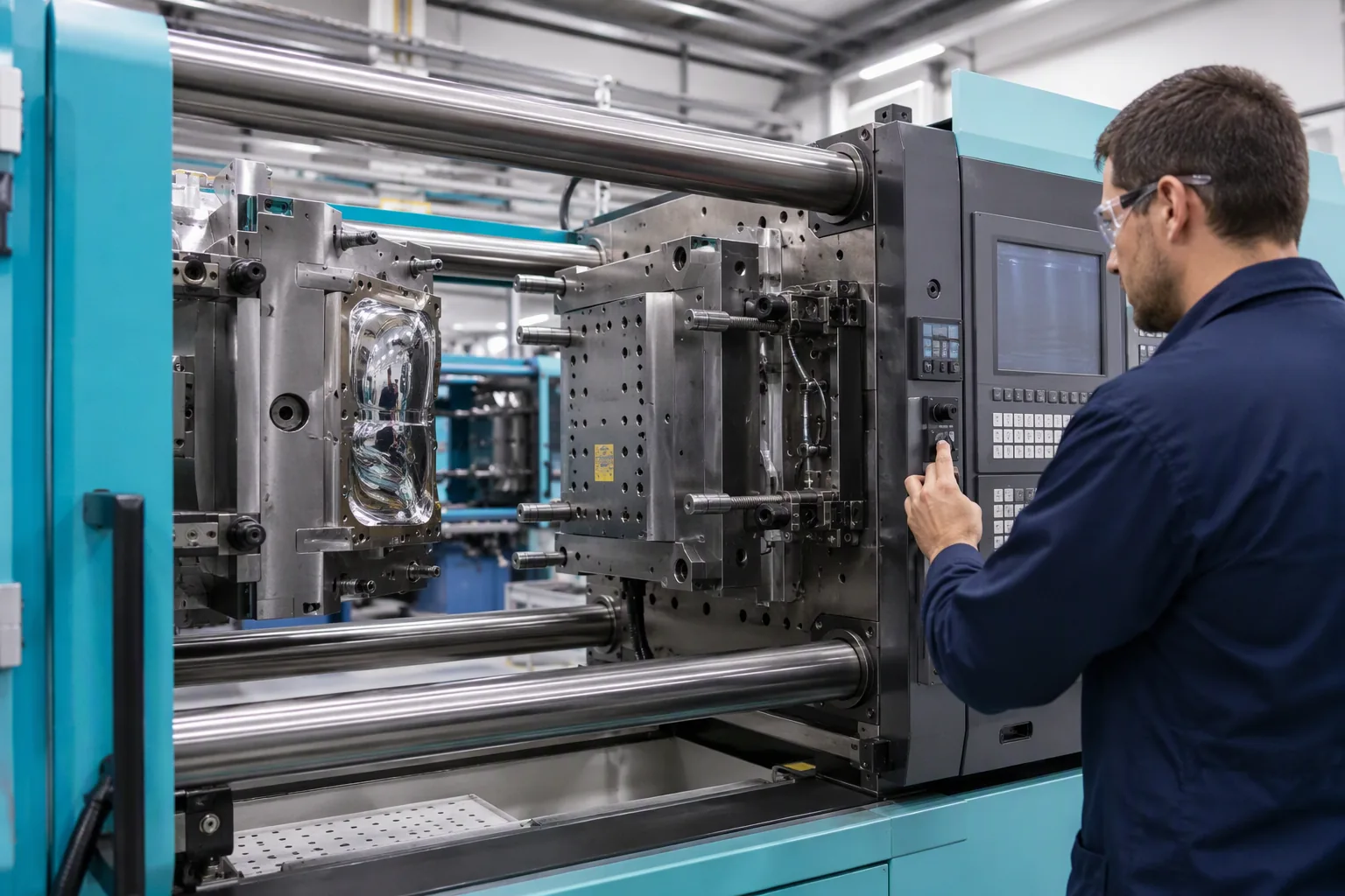
Injection moulding machine with an open mould tool
The Development Step Table
Step
Activity
1
Define the part function and load
2
Select the material
3
Design the part geometry
4
Design the mould
5
Manufacture the mould
6
Trial the first parts
7
Approve or modify
The Mould Design Table
Element
Consideration
Cavity count
Output against tooling cost
Gate location
Weld line and flow balance
Runner system
Material efficiency
Cooling layout
Cycle time and warp
Ejection
Part deformation risk
Venting
Burn marks and short shots
Steel selection
Tool life and finish
The Geometry Table
Feature
Guideline
Wall thickness
Uniform where possible
Ribs
Thickness below the wall
Bosses
Supported and radiused
Radii
Avoid sharp internal corners
Draft
Sufficient for release
Living hinge
Correct thickness and orientation
The Trial Table
Trial
Purpose
First shot
Fill and shape check
Dimensional check
Against the drawing
Functional check
Fit with webbing
Load test
Against the rating
Cycle test
Repeated operation
Environmental test
Cold and heat exposure
The Approval Table
Check
Requirement
Dimensions
Within tolerance
Function
Meets the load and cycle requirement
Fit
Works with the specified webbing
Appearance
Matches the reference
Material
As specified, verified
Marking
Cavity and material marks present
The Approval Record Table
Field
Purpose
Part number and revision
Version control
Mould identifier
Traceability
Material grade
Specification
Trial results
Evidence
Reference sample
Physical standard
Approval date and approver
Accountability
The Modification Table
Trigger
Action
Dimension outside tolerance
Mould correction
Warping
Cooling or gate adjustment
Weld line in a critical area
Gate or flow change
Weak feature
Geometry revision
Poor fit with webbing
Interface revision
Process Parameters and Moulding Quality
The same mould and the same material can produce a strong part or a fragile one. The difference is the process window: the temperatures, pressures, and times that the machine is set to.
The Parameter Table
Parameter
Effect
Melt temperature
Flow and weld strength
Mould temperature
Surface and shrinkage
Injection pressure
Fill completeness
Holding pressure
Shrinkage and sink marks
Hold time
Gate seal and weight
Cooling time
Cycle time and warp
Injection speed
Weld line and orientation
The Defect Table
Defect
Likely cause
Short shot
Low pressure or cold mould
Flash
Excess pressure or worn mould
Sink mark
Insufficient holding pressure
Warping
Uneven cooling or packing
Burn mark
Trapped gas or high speed
Weld line weakness
Low melt temperature
Silver streaks
Moisture in the resin
Dimensional drift
Inconsistent mould temperature
The Process Window Table
Condition
Risk
Within the window
Consistent parts
At the edge
Intermittent defects
Outside the window
Systematic failure
The Setup Record Table
Field
Purpose
Machine and mould
Identification
Material and grade
Specification
Parameters used
Reproducibility
Verified by
Accountability
Date
Chronology
The Material Handling Table
Control
Reason
Drying before moulding
Prevents silver streaks and weak parts
Sealed containers
Prevents moisture pickup
Controlled regrind ratio
Maintains properties
Segregation by grade
Prevents cross-contamination
Colour change purging
Prevents contamination
The Process Drift Table
Drift
Symptom
Rising mould temperature
Longer cooling, warping
Worn screw or barrel
Inconsistent shot weight
Blocked vent
Burn marks
Worn check valve
Short shots
Contaminated resin
Weak welds
Inspection and Testing
Moulded hardware is inspected for dimensions and appearance, and tested for the functions that the customer will actually exercise: holding load, adjusting, releasing, and surviving repeated use.
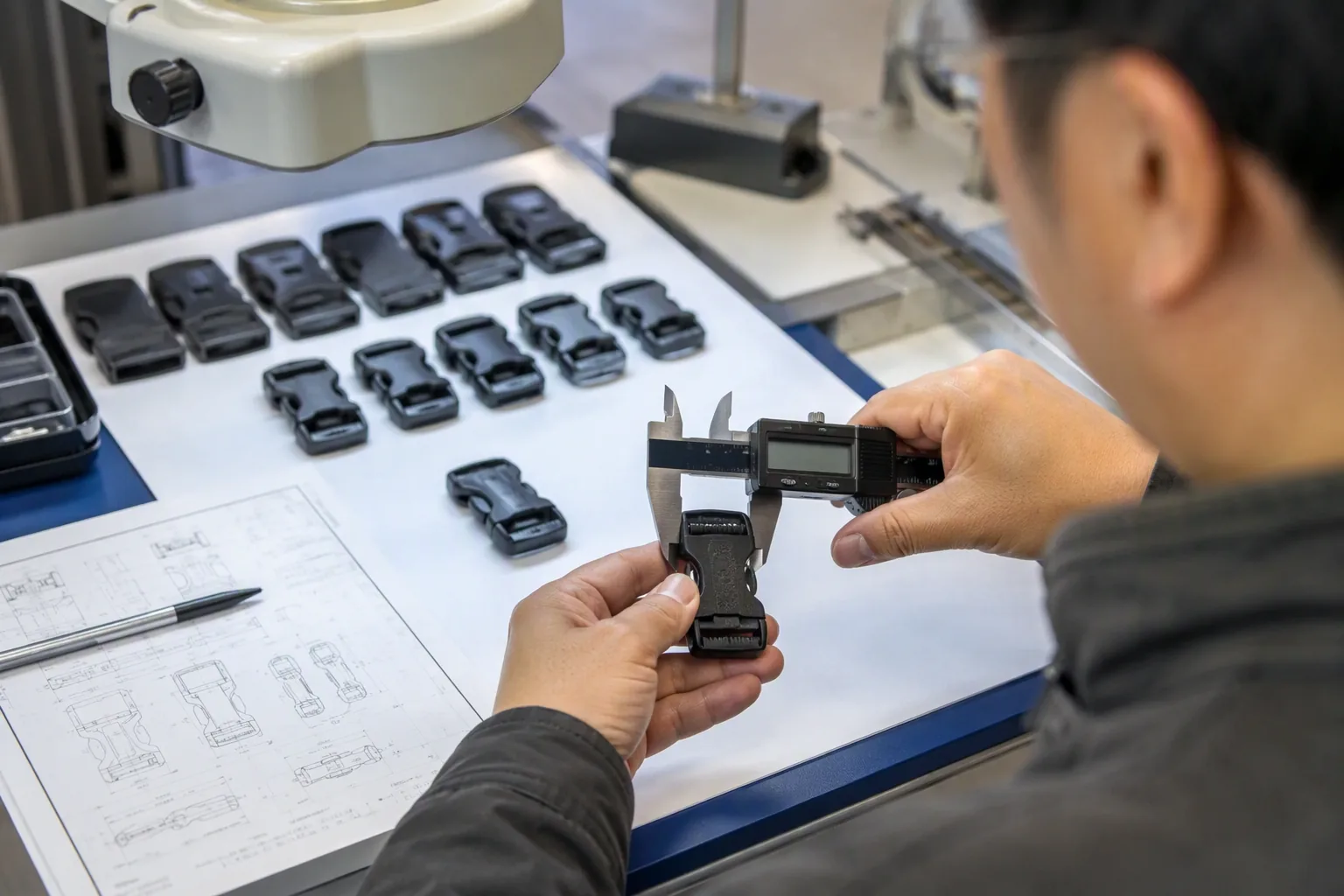
Technician measuring a moulded buckle against a reference sample
The Inspection Table
Check
Method
Critical dimensions
Callipers or gauges
Webbing fit
Assembly with the specified strap
Gate and flash
Visual
Weld line
Visual, positioned clear of stress
Colour
Against the reference
Marking
Visual verification
The Test Table
Test
Purpose
Tensile pull
Buckle and ring strength
Slip test
Adjuster hold under load
Cycle test
Repeated open and close
Cold impact
Low-temperature brittleness
Heat ageing
Creep and deformation
UV exposure
Outdoor durability
Salt spray
Metal component corrosion
The Sampling Table
Stage
Approach
First article
Full dimensional and functional
In-process
Periodic visual and dimensional
Final inspection
Sampled per AQL level
Pre-shipment
Confirmation against the sample
The Failure Criteria Table
Failure
Interpretation
Buckle opens under load
Below the load rating
Adjuster slips
Grip geometry or material
Cracking at a corner
Stress concentration
Hook gate deforms
Insufficient section
Colour mismatch
Masterbatch or process
Warping
Cooling or packing
The Reference Sample Table
Sample
Purpose
Approved first article
Dimensional and visual standard
Production sample
Ongoing comparison
Field-returned part
Failure analysis
The Traceability Table
Question
Record
Which mould made this?
Cavity mark
When was it made?
Date code
What material was used?
Material code
Which batch shipped?
Packing record
Tolerance, Fit and Assembly
A buckle that is correct in isolation can still fail in the bag, because the interface with webbing, the assembly process, and the load path all impose their own requirements.
The Tolerance Table
Feature
Approach
Critical interface
Tight tolerance
Functional clearance
Controlled range
Cosmetic surface
Moderate tolerance
Non-critical
Wide tolerance
The Fit Table
Interface
Requirement
Buckle to webbing width
Snug without binding
Ladder lock to webbing thickness
Grip without cutting
Cord lock to cord
Hold without damage
Hook to D-ring
Free movement, secure closure
Zipper pull to slider
Positive attachment
The Assembly Table
Operation
Risk
Threading webbing
Twisting or misalignment
Setting a rivet or snap
Over-compression of plastic
Heat sealing
Local melting
Bar tacking
Needle strike on plastic
Press fitting
Cracking
The Load Path Table
Path
Design consideration
Strap to buckle to strap
Continuous load path
Bag body to attachment point
Reinforced interface
Handle to bag
Load spread
Compression strap
Tension distribution
The Stack-Up Table
Contributor
Tolerance source
Moulded part
Moulding tolerance
Webbing
Width and thickness
Assembly
Positioning
Stitching
Placement variance
The Complaints Table
Complaint
Likely interface issue
Strap slips
Webbing thickness outside range
Buckle stiff
Clearance too tight
Buckle rattles
Clearance too loose
Webbing fraying at the buckle
Sharp internal edge
Hardware pulls out
Attachment not reinforced
Cost Structure and Sourcing
Moulded hardware is a low-value, high-dependency purchase. The unit price matters, but the real cost is decided by the mould investment, the order quantity, and the cost of a failure that reaches the customer.
The Cost Element Table
Element
Character
Mould cost
One-off, significant
Unit material cost
Volume-driven
Machine time
Cycle time and cavity count
Labour
Setup and inspection
Colour change
Setup and purging
Packaging
Protection and counting
Testing
Sample and periodic
The Volume Table
Quantity
Effect
Very low
Mould cost dominates
Low
Higher unit price
Medium
Unit price falls
High
Unit price approaches material cost
Very high
Multi-cavity mould justified
The Mould Ownership Table
Arrangement
Consequence
Buyer-funded, buyer-owned
Buyer bears cost, controls use
Buyer-funded, factory-held
Off-tool amortisation
Factory-funded
Cost inside the unit price
Shared
Negotiated split
The Supplier Table
Supplier type
Character
Dedicated hardware moulder
Focused, consistent
General moulder
Flexible, less specialised
Trading company
Convenience, less visibility
Integrated bag factory
Control, less specialisation
The Selection Table
Criterion
Why it matters
Moulding capability
Tonnage and precision
Material handling
Drying and regrind control
In-house tooling
Faster modification
Testing capability
Verification without outsourcing
Quality system
Consistency
Capacity
Delivery reliability
The Cost of Failure Table
Failure
Cost
Sorted at the factory
Labour and delay
Returned by a customer
Full bag value
Recall
Very high
Brand damage
Long-term
Repeat failure
Lost program
The Sourcing Checklist Table
Item
Verification
Material grade
Certificate or test report
Mould identification
Cavity marks present
Sample approval
Reference part retained
Test data
Load, cycle, and temperature
Regrind policy
Stated in writing
Change notification
Written undertaking
Buyer note: Hardware is where a program is most likely to be quietly substituted, because a different grade of the same colour looks identical in the bag. Write the material grade, the regrind limit, and a change-notification obligation into the purchase order, and re-verify the part after any supplier, mould, or material change. A substitution caught at the factory costs a sample; the same substitution caught in the field costs the program.
Quality Control and Problem Containment
When a moulded part fails, the priority is to stop the failure from reaching customers and to find whether the cause is the design, the mould, or the process.
The Containment Table
Step
Action
1
Stop shipment of the affected batch
2
Identify the batch range by cavity and date code
3
Quarantine stock at the factory and in transit
4
Notify the buyer with the scope
5
Inspect and sort
6
Decide rework, replace, or release
The Investigation Table
Question
Evidence
Which cavity produced it?
Cavity mark
Which material batch?
Material certificate
Which machine and parameters?
Setup record
When was it made?
Date code
Is it design or process?
Failure analysis
The Cause Table
Symptom
Probable cause
Cracking at a corner
Design stress concentration
Cracking across a weld line
Low melt temperature
Buckle opens under load
Geometry or material
Warping
Cooling imbalance
Colour variation
Masterbatch or process
Brittle in cold
Wrong grade
The Corrective Action Table
Cause
Action
Design
Revise the geometry
Mould
Correct the tool
Process
Reset and re-verify the window
Material
Revert to the specified grade
Regrind
Reduce the ratio
Storage
Change the packing and environment
The Verification Table
Action
Verification
Geometry revised
New first article approved
Tool corrected
Dimensional report
Process reset
Setup record and samples
Material reverted
Certificate and test
Batch sorted
Sort report
The Change Notification Table
Change
Requirement
Material grade
Prior notification and approval
Supplier or plant
Prior notification
Mould modification
Approval before production
Regrind ratio
Approval required
Colour source
Notification
Stability, Storage and Shelf Life
Moulded parts are durable, but not inert. Moisture absorption, sunlight, heat, and stress during storage can change a part before it is ever assembled.
The Storage Table
Condition
Effect
Direct sunlight
UV degradation
High humidity
Moisture absorption in nylon
High temperature
Creep and deformation
Heavy stacking
Distortion
Contact with solvents
Stress cracking
The Material Sensitivity Table
Material
Sensitivity
POM
Low moisture, sensitive to acids
Nylon
High moisture absorption
PP
Low moisture, UV sensitive
ABS
UV and solvent sensitive
TPU
Heat and hydrolysis sensitive
The Shelf Life Table
Consideration
Guidance
Sealed packaging
Protects from moisture and dust
Bagged and dated
Enables rotation
Rotation on issue
Uses oldest first
Container climate
Ventilation and shade
Handling
Avoid impact on cold parts
The Pre-Assembly Check Table
Check
Reason
Visual condition
Detects damage in storage
Webbing fit trial
Confirms dimensional stability
Function test
Confirms no deformation
Colour check
Confirms no fading
The Returns Analysis Table
Return pattern
Likely cause
Winter failures
Cold brittleness
Failures after months in sun
UV degradation
Early failures only
Design or process
Random across batches
Material inconsistency
Concentrated in one cavity
Tool problem
The Moulded Hardware Checklist
Moulded buckles undergoing a load test on a spring testing rig
Specification
Item
Done
Function defined before design freeze
☐
Load case stated
☐
Material and grade specified
☐
Colour reference agreed
☐
Critical dimensions toleranced
☐
Webbing compatibility stated
☐
Marking requirement defined
☐
Mould and Approval
Item
Done
Mould designed for the part function
☐
Gate and cooling reviewed
☐
First article dimensionally checked
☐
Functional test completed
☐
Load test against the rating
☐
Cycle test completed
☐
Environmental exposure tested
☐
Reference sample retained
☐
Approval recorded with revision
☐
Process Control
Item
Done
Material dried before moulding
☐
Regrind ratio limited and recorded
☐
Mould temperature controlled
☐
Parameters recorded and reproducible
☐
Cavity marking present
☐
Date coding applied
☐
Batch traceability maintained
☐
Inspection and Testing
Item
Done
Critical dimensions checked in process
☐
Webbing fit verified
☐
Visual standard applied
☐
Sampled load test performed
☐
Cycle test performed periodically
☐
Results recorded
☐
Sourcing and Change
Item
Done
Grade written into the purchase order
☐
Change notification required
☐
Supplier verified for capability
☐
Failures contained by cavity and date
☐
Corrective action verified
☐
Storage conditions controlled
☐
The Eight Rules
Rule
Reason
Specify the hardware before the bag is designed
Interface constraints rule out options
Write the material grade into the purchase order
Colour hides substitution
Require cavity and date marks
Nothing can be traced without them
Limit regrind in writing
Excess regrind weakens parts
Record the process window
Reproducibility depends on it
Test function, not only dimensions
A part can measure correctly and fail
Re-approve after any change
Supplier and material changes shift behaviour
Keep a reference sample
The physical standard outlives the paperwork
FAQ
Which plastic is best for backpack buckles?
Polyoxymethylene, often called acetal or POM, is the usual choice for buckles, ladder locks, and adjusters because it combines stiffness, low friction, and good fatigue resistance, which is what a part needs when it is repeatedly opened and closed under tension. Nylon is used where higher impact strength is required and can tolerate its greater moisture sensitivity. Polypropylene appears in parts that need to flex, such as some cord locks and hinges. The right answer depends on the load, the temperature range, and the exposure, so the material should be selected against the application rather than by habit.
Can we copy an existing buckle from another brand?
Copying the shape gives you the geometry but not the material, the wall thickness intent, the gate position, or the process window, so a copy often fails where the original does not. It also raises design and intellectual property questions that are worth resolving before tooling is cut. If an existing part works, the productive approach is to use it as a functional benchmark, measure its critical dimensions and load behaviour, and then design a part that meets the same requirements with a documented material and a mould that is set up to produce it consistently.
What tests should moulded hardware pass before approval?
At minimum, a dimensional check against the drawing, a functional test with the actual webbing the part will be used with, a tensile pull test against the stated load rating, and a cycle test that reproduces the number of open-and-close operations expected in service. Where the bag is sold into a cold market, a cold impact test is important because some grades embrittle at low temperature. Where it is used outdoors, UV exposure matters. The approved first article should be retained as the physical reference for all future production.
How much regrind is acceptable?
It depends on the material and the application, but the principle is that regrind degrades the resin each time it is processed, which reduces impact strength and can shift dimensions. Many programs allow a limited proportion of clean, same-material regrind for non-critical parts and none at all for load-bearing components. Whatever the rule, it should be stated in writing in the purchase order and verified periodically, because regrind is invisible in the finished part and is one of the most common causes of a batch that breaks where an earlier batch did not.
Why does a buckle break at a corner rather than in the middle?
Corners concentrate stress. A sharp internal corner creates a point where the load is amplified, and repeated flexing starts a crack there long before the rest of the part is near its limit. The remedy is geometric: a generous internal radius, a slightly thicker section at the corner, or a rib that carries the load around the corner rather than through it. Because the failure is a design issue rather than a material one, changing the resin alone usually moves the failure somewhere else rather than removing it.
How do we handle a batch that turns out to be brittle?
Contain first, investigate second. Identify the affected batch by the cavity and date codes on the parts, quarantine stock at the factory and anything in transit, and notify the buyer with the scope so that a decision can be made about sorting or replacement. Then determine whether the cause is the material batch, an excessive regrind ratio, moisture in the resin, or a process parameter that has drifted. The fix is verified by re-testing, and the batch decision follows the evidence rather than the assumption.
Does the mould need to be owned by the buyer?
It depends on who paid for it and what protection the buyer needs. If the buyer funds the tooling and wants exclusivity, ownership is the cleanest arrangement because it supports the right to move the tool to another moulder. If the factory funds it, the cost is usually recovered inside the unit price and ownership normally stays with the factory, which means the buyer has less control over where the part is produced. Whatever the arrangement, the ownership, the use restriction, and the custody should be recorded in writing when the mould is ordered.
What causes colour variation between batches?
Usually the masterbatch, the dosing, or the process. A different masterbatch carrier, an inconsistent dosing ratio, an incomplete purge between colours, or a mould temperature change can all shift the shade. Because the colour masterbatch can also affect mechanical properties, a colour change is not purely cosmetic and the part should be re-verified after it. The practical control is an approved colour reference held by the moulder, a dosing record, and a purge procedure, with the finished part compared against the reference at each production start.
How is moulded hardware costed?
The mould itself is a one-off cost that is either charged separately or amortised across the expected order quantity. The unit cost then reflects the material, the machine time determined by the cycle time and the number of cavities, the labour for setup and inspection, the colour change if applicable, and packaging. Quantity has a large effect because a multi-cavity mould spreads the machine time across more parts, so a very small order carries a high unit price while a large one approaches the material cost. Testing and sample approvals are usually charged separately.
Conclusion
Moulded hardware is where a backpack’s reliability is decided by the smallest parts it contains. A buckle that holds, an adjuster that grips, and a hook that does not deform under load are the product of a material chosen for the application, a mould designed for the load path, a process held inside a recorded window, and a part approved against a physical reference rather than against a supplier’s catalogue photograph.
The controls that deliver this are straightforward. Specify the hardware before the bag is designed, so that the strap, the webbing, and the attachment point do not constrain the part into a compromise. Write the material grade and the regrind limit into the purchase order, because colour makes substitution invisible.
Require cavity and date marks so that any failure can be traced to the tool and the batch that produced it. Record the process window so that a good batch can be reproduced rather than repeated by luck. Test function as well as dimensions, since a part can measure correctly and still fail in the field. Re-approve after any change of supplier, mould, or material, and keep the approved first article as the standard that outlives the paperwork.
For factories, disciplined moulded-hardware control removes one of the most common causes of a good bag coming back: a small part that was never specified for the load it would carry. A plant that can show a material certificate, a mould identifier, a process record, and a tested first article is in a position to defend its product when a return is investigated, and to fix the cause rather than the symptom.
For buyers, the practical starting point is to ask three questions before the tooling is cut: which grade of resin is specified and why, what load does the part have to hold, and how will the finished part be verified against that requirement. The answers determine whether the hardware will still be working two seasons from now, and they cost nothing to ask early.